Department Microstructure and Residual Stress Analysis
Beamline Optical Lay-out
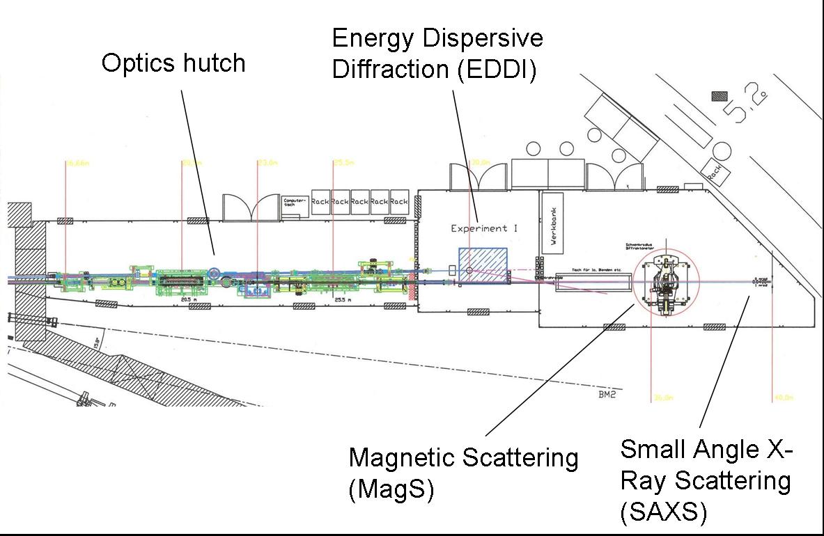
The synchrotron beam generated by the 7T-Wiggler is devided into a monochromatic and a white beam. The former is used for the magnetic and the small angle scattering experiment, the latter for the EDDI experiment.The general layout of the two beamlines is shown in the following figure.
Photos of the optics hutch: upstream view, downstream view
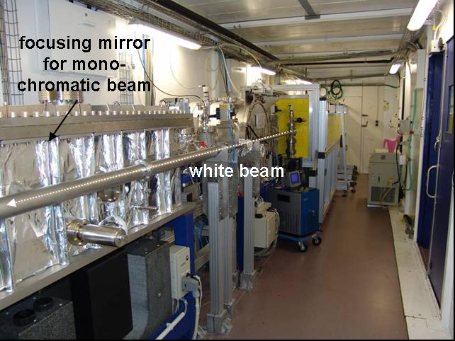
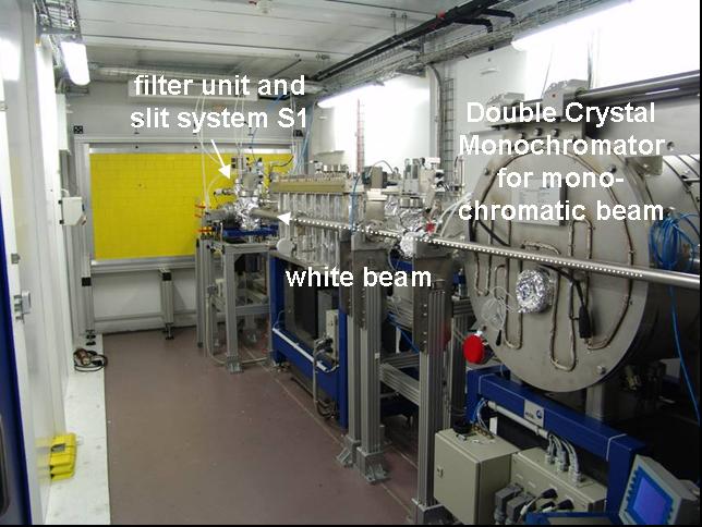
The white beam passes a nearly 30 m evacuated pipe and a few optical components up to the place of the experiment. A mask limits the beam diameter to make sure it will not touch the pipe under any circumstances. Slits and filter system provide the experimenter with the beam characteristics required. A quick photon shutter allows defined and short exposure times of the sample.
| Optical Component | Description | Approx. distance to source [m] |
| source | wiggler 7T, 7 periods, height of source (electron beam vertical diameter) is about 25 µm | 0 |
| mask | absorber mask to reduce the beam to 3.9 mm x 3.9 mm, resp. 0.2 mrad x 0. mrad | 19.3 |
| white beam slit (slit system S 1) | tungsten alloy, thickness 10 mm, edge of blade rounded to R = 5 mm, flatness within 2 µm | 26.8 |
| filter 1 | filter bank with four different filters, attenuator material is Al with thickness of 1 mm, 2 mm, 3 mm and 4 mm | 27.1 |
| filter 2 | sheets and pieces of C, Cu, Al, Fe are available | 29.0 |
| slit system S 2 | tungsten alloy, thickness 10 mm, flat edges, horizontal and vertical tilt and translation for optimal alignment | 29.5 |
| quick photon shutter | x-ray shutter system that allows exposure times in the sub-second range | 29.5 |
| center of diffractometer | theta-thata diffractometer MZ VI with 4- and 5-axes sample manipulator units | 30.0 |
Beamline Performance Data
The beamline is located at the most powerful insertion device at Bessy and thus provides excellent flux for energies from 10 to 80 keV. Even beyond 80 keV up to 150 keV the flux may be sufficient for many experiments as first experiments show.
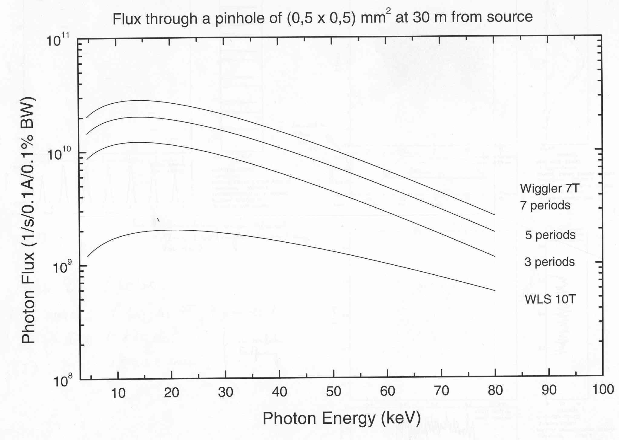
Fig. 1: Calculation of flux and comparison to other possible sources
Investigations in respect of penetration depth have been made for a Ni-base alloy. In transmission, a 15 mm thick part gave reasonable diffraction patterns. The corresponding diagrams are shown in section first experiments).
The vertical beam divergence is given by the size of the source (25 µm), the source to experiment distance (30 m) and the S2 slit gap. So the divergence at a maximum slit gap of 4 mm is 0.13 mrad which is even smaller than the natural vertical beam divergence of 0.3 mrad.