Abteilung Mikrostruktur- und Eigenspannungsanalyse
ETA-Diffraktometer
Die folgende Abbildung zeigt eine schematische Darstellung des Diffraktometers. Es arbeitet nach dem Prinzip des SEIFERT Theta-Theta-Diffraktometers MZ VI. In der Grundkonfiguration ist die Probe horizontal ausgerichtet, während sowohl die Röntgenröhre als auch der Detektor in der vertikalen Beugungsebene gedreht werden können. Damit entspricht das Arbeiten in diesem Modus der konventionellen Omega-Geometrie, wie sie in der RSA definiert ist. Alle Probendrehungen basieren auf einem zweiten 1-Kreis-Goniometer, das in der horizontalen Ebene arbeitet, d.h. seine Achse phi1 und die Theta'/Theta-Achsen stehen senkrecht zueinander. Der Winkel psi zwischen der Oberflächennormalen und g(hkl) wird mit Hilfe eines Eulerschen Wiegesegments eingestellt, das in einem Winkelbereich zwischen 0° und 90° arbeitet und so auf das phi1-Goniometer aufgesetzt wird, dass die psi- und die phi1-Achse einen Winkel von 90° einschließen.
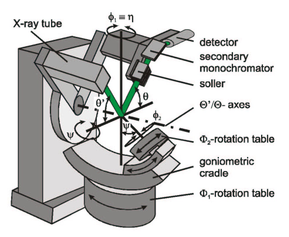
Eine Drehung um phi1 entspricht genau der Drehung der Probe um den Streuvektor g(hkl), der um den Winkel psi gegen die Oberflächennormale geneigt ist. Der Azimut phi von g(hkl) in Bezug auf das Probensystem wird durch einen Drehtisch phi2 innerhalb des Eulerschen Wiegesegments eingestellt. Allgemein betrachtet handelt es sich bei dem ETA-Diffraktometer um ein 5-Kreis-Diffraktometer, das sich von einer herkömmlichen 4-Kreis-Eulerschen Wiege durch die zusätzliche Achse phi1 für die Drehung der Wiege (Segment) senkrecht zu den θ'/θ-Achsen unterscheidet. Diese phi1-Achse ist jedoch der notwendige zusätzliche Freiheitsgrad, der für die direkte Realisierung der eta-Drehung benötigt wird. Für die Analyse von Dünnschichtspannungen bei streifendem Einfall können verschiedene optische Elemente wie Sollerblenden und primäre bzw. sekundäre Monochromatoren sowohl in den einfallenden als auch in den gebeugten Strahl platziert werden. Die Probenpositionierung erfolgt über x-, y- und z-Translationstische und wird von einem System aus einem Laser und einer CCD-Kamera gesteuert, die auf das Zentrum des Diffraktometers fokussiert sind, das durch den Schnittpunkt aller Rotationsachsen definiert ist.
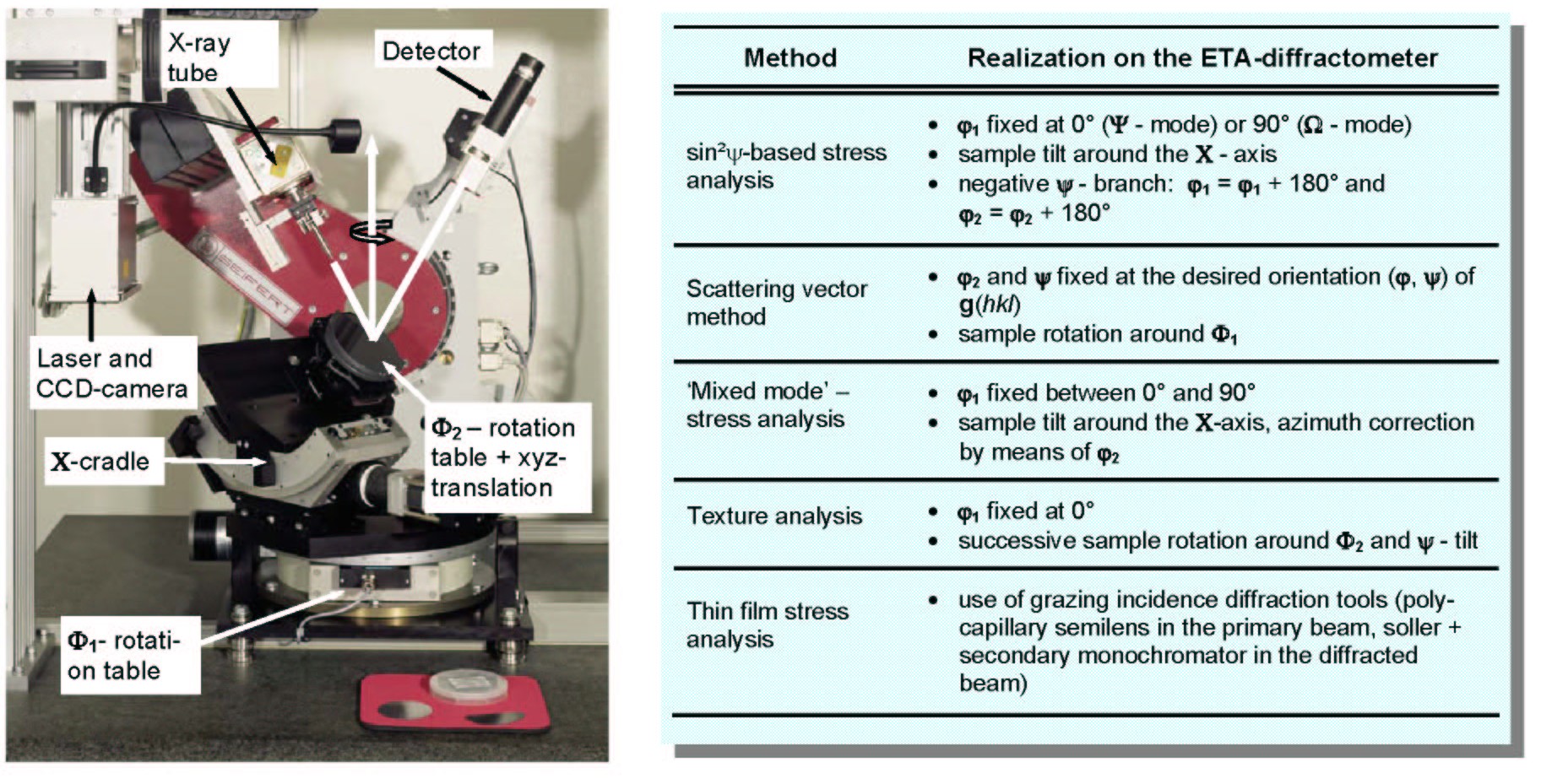
Das Foto unten zeigt den Aufbau des ETA-Diffraktometers in unserem Labor. Die nebenstehende Tabelle gibt einen Überblick über alle gängigen Beugungsmethoden, die mit dem ETA-Diffraktometer durchgeführt werden können.