Joint Research Group Macromolecular Crystallography
How to Align a Crystal with STAC
STAC can calculate the motor values for all requested orientations if two sets of information are provided, namely:
- How the crystal is mounted on the goniometer, described by the descriptor, and
- What is its initial orientation with respect to the X-ray beam, described by the orientation matrix.
The descriptor file .sav is created automatically by the control software mxCuBE and stored in the process directory of the users home directory.
The orientation matrix is an output of the processing of diffraction images and therefor has to be provided by the user.
Startup
- Mount the crystal you want to align.
- Start STAC by launching the command run_stac.
- Select the tab <input for re-orientation> within STAC and clear the input mask with the <NEW XTAL> button if necessary.
Generate the orientation matrix
- Pre-characterize the crystal, i.e. take few images for determination of orientation matrix
- Simple characterization: single wedge data collection of 4 successive images
- Recommended characterization: disguised double-wedge data collection with 4 sucessive images each with an oscillation range below crystal mosaicity
- Index and integrate the test images with the standard data processing software packages available at the beamlines to get the orientation matrix.
For detailed information on how to configure and operate XDS or iMOSFLM follow the corresponding links.
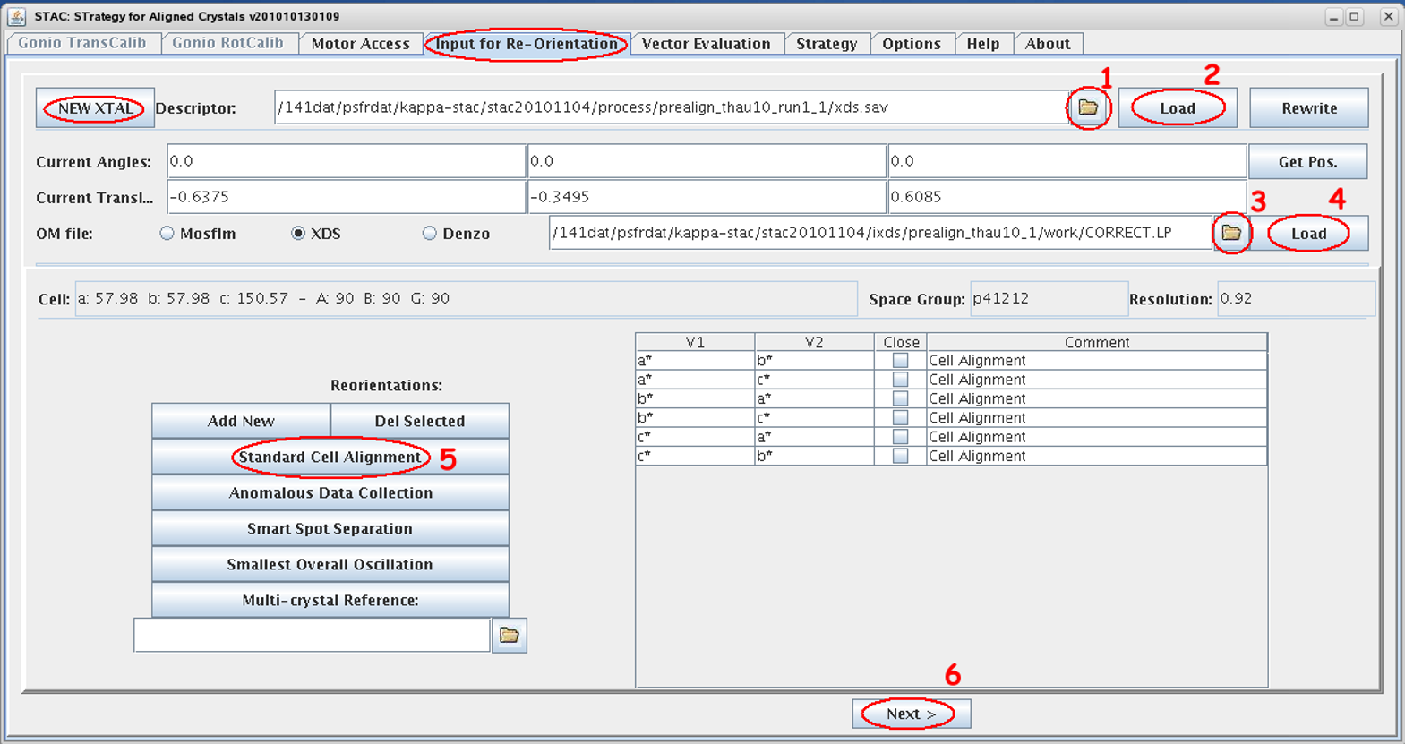
- Select the appropriate descriptor file *.sav by browsing to the process sub-directory tree of the acquired images. In case you did the double-wedge go for run1!
- Load its content, i.e. the geometrical constrains of the pre-characterization images, and compare the displayed values with your mxCuBE input.
- Select the appropriate orientation matrix (xds:CORRECT.LP, MOSFLM:bestfile.par) by browsing to the sub-directory tree of the acquired images.
- Load its STAC relevant content and compare lattice constants and spacegroup with your processing result.
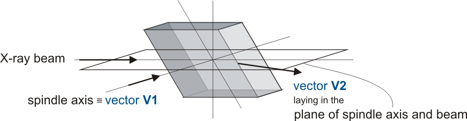
- Select the geometry you are aiming for, for a detailed description please refer to Alignment Scenarios
- All possible orientation which fulfill your selection will be listed
- You can add or delete special orientation with <Add New> or <Del Selected>
- If certain orientations are highlighted only these will be calculated
otherwise all will be processed
- Start calculation by selecting <Next>
- Select the solution from the table in the <Vector Evaluation> tab which seems to be the most appropriate
- Note κ > 240 is not accessible in our setup due to collision management
- In case you dont get any solution retry calculation by additionally checking the <close> box, to get an alignment close to the required one
- Move motors with translation correction to the corresponding values by selecting <mv selected>
Collect data
Start data collection from aligned crystal or go for a second set of characterization images to calculate a strategy for the aligned crystal.
Double-check omega-start value in mxCuBE!